VMware NSX is the network virtualization platform that enables the implementation of virtual networks on your physical network and within your virtual server infrastructure. VMware NSX Data Center delivers virtualized networking and security entirely in software, completing a key pillar of the Software-defined Data Center (SDDC), and enabling the virtual cloud network to connect and protect across data centers, clouds, and applications.
NSX consist of multiple components which can be categorized under different planes like Management, Control and Data plane. In this blog we will concentrate on the data plane that is Logical Switches and control plane that is Distributed Logical Router (DLR).
Logical Switch
Logical switches have similar functionality to that of a physical switch, they allow the isolation of your applications and tenants for security and other purposes. A logical switch creates a broadcast domain to allow such an isolation of virtual machines. Using logical switches, you can now not only create VLANs that are like a physical switch, but also make them span across large compute clusters. This now allows you to migrate your virtual machines using vMotion without range limitations of the physical network. The logical switch is mapped to a VXLAN that encapsulates the traffic over the physical network.
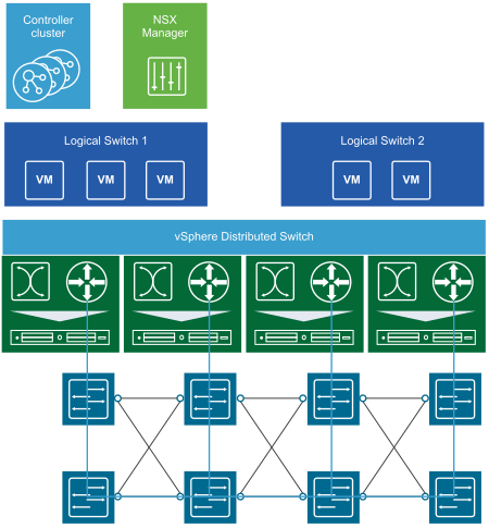
Creating Logical Switch
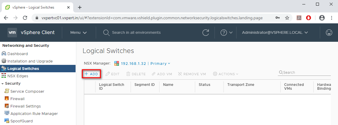
To create Logical Switch, navigate to vCenter Web Client – Network and Security – Logical switches – Click on +ADD sign as shown below
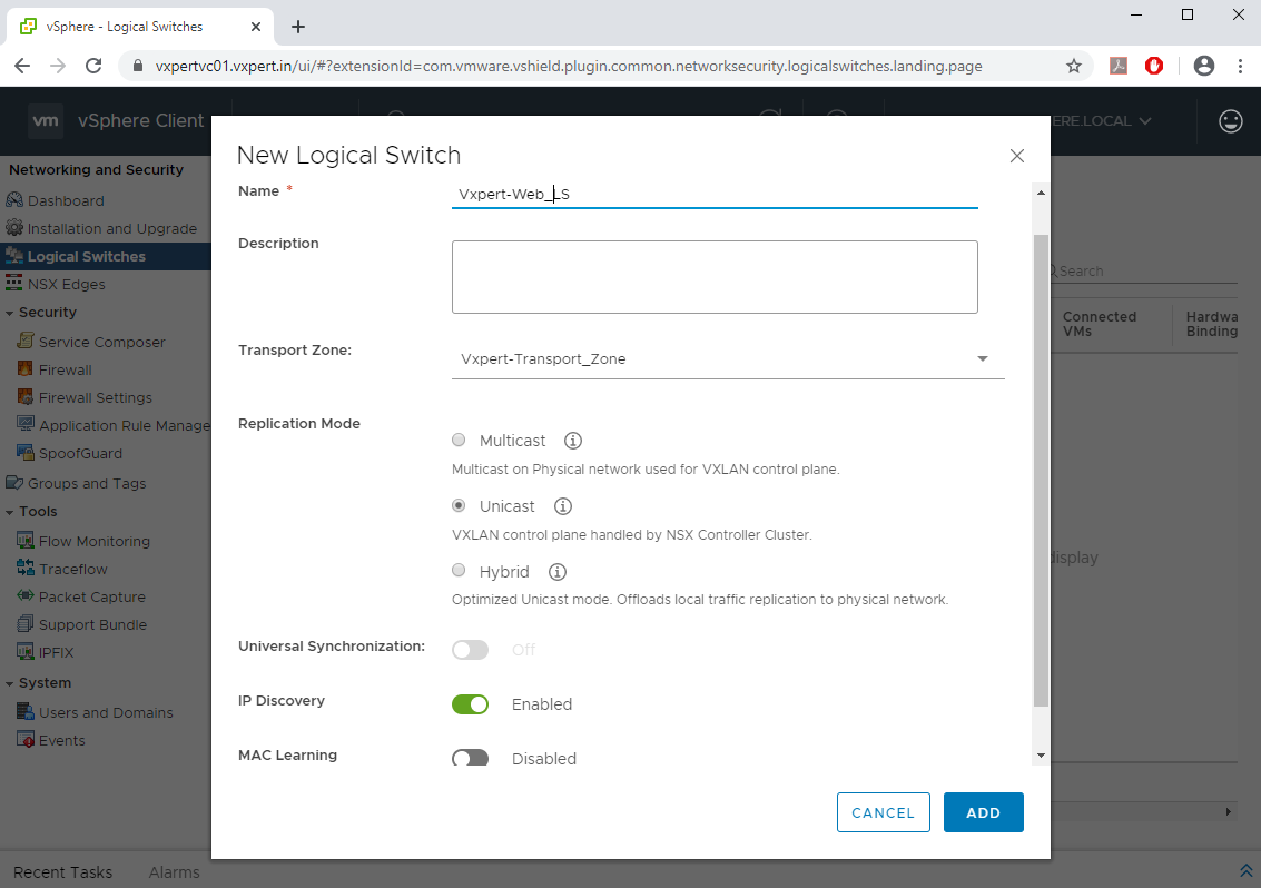
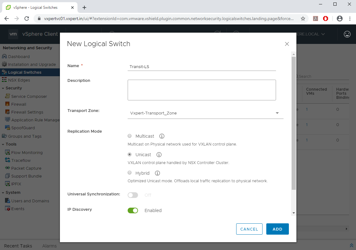
Select name of Logical Switch, Transport Zone that part of and replication mode and click OK
Same way creates two more Logical switch for App and DB zone.
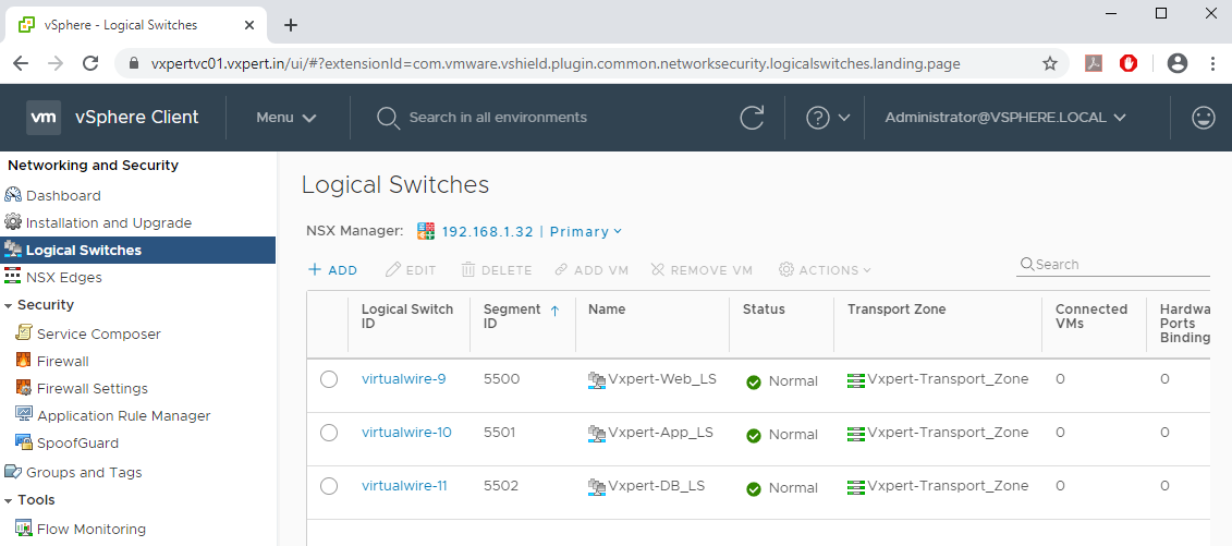
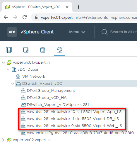
Also, you can see different port groups are created for each Logical Switches we created
Add Virtual Machine to Logical Switch
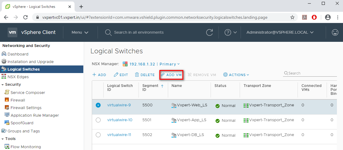
To add Virtual Machine to Logical Switch, navigate to vCenter Web Client – Network and Security – Logical switches – Click on ADD VM sign as shown below
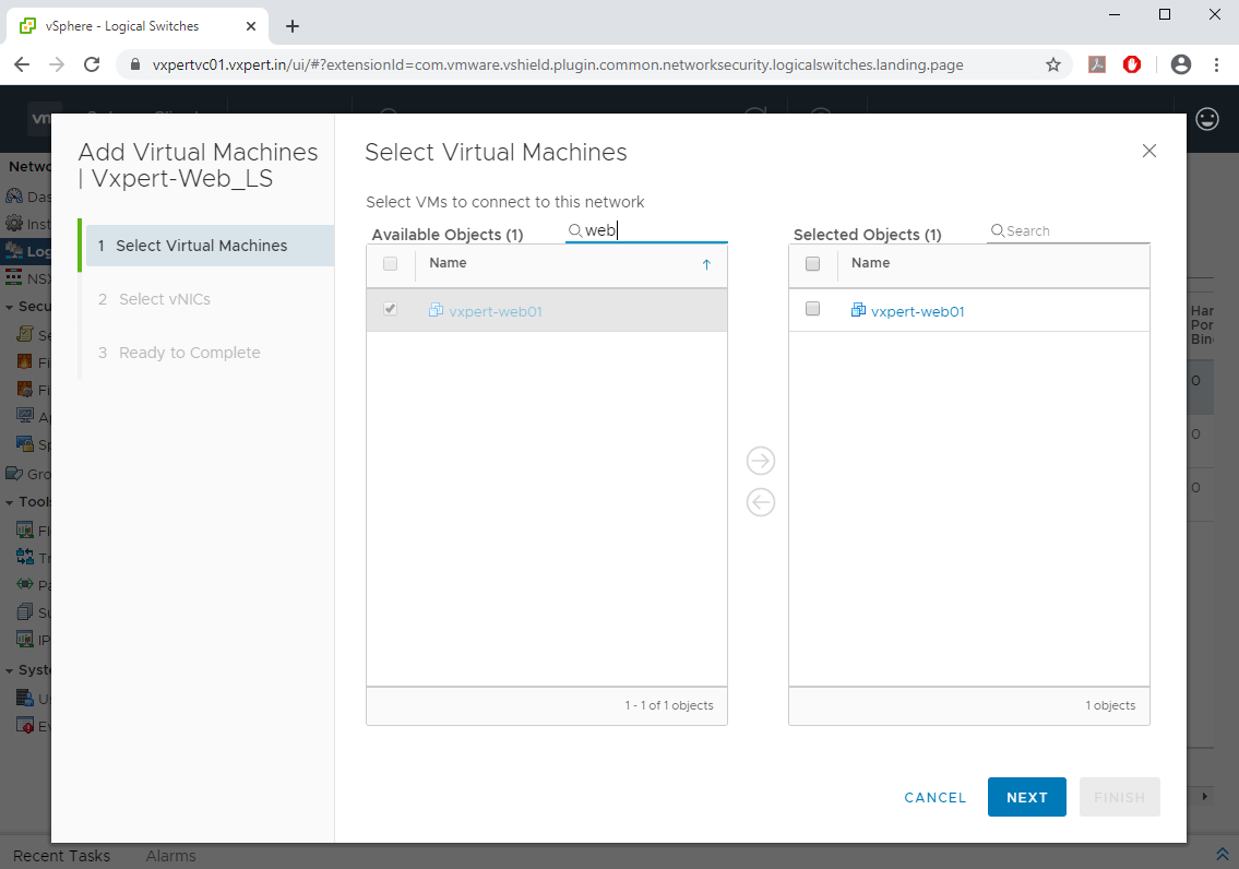
From the inventory select the required VM and click Next
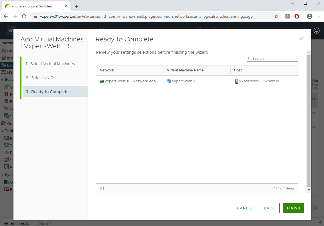
Select the Network Adapter and click Next

Click Finish to complete
Also, you can directly edit the Virtual machine and select the distributed port group created for respective Logical Switch. Repeat the same steps for App and DB VMs. Once complete you can see the number of VMs connected to each Logical Switch.

Distributed Logical Router (DLR)
A distributed logical router (DLR) is a virtual appliance that contains the routing control plane, while distributing the data plane in kernel modules to each hypervisor host. The DLR control plane function relies on the NSX Controller cluster to push routing updates to the kernel modules. DLR consist of two components
- DLR Control VM – This is the control plane of DLR, and the role is to peer with NSX Edges and push the routes to ESXi kernel using NSX controllers.
- DLR Kernel Module – This is the data plane of DLR, these modules are pushed to ESXi kernel during host preparation
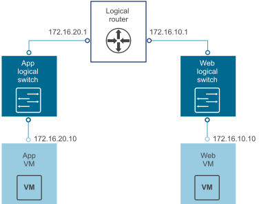
Deploy Distributed Logical Router
To add Distributed Logical Router Control VM, navigate to vCenter Web Client – Network and Security – NSX Edges – Click on +ADD sign as shown below and select Distributed Logical Router
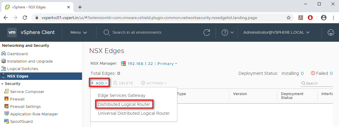
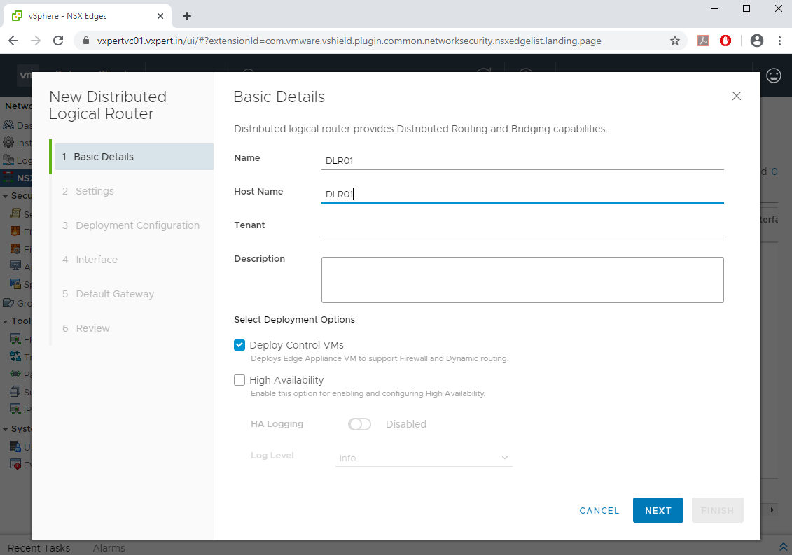
Select Name, Host Name and Deployment option as Deploy Control VM, this will deploy Edge Appliance VM to support Firewall and Dynamic Routing and click Next.
Note: – You can select High Availability option for your production infrastructure, and this will create one more Control VM
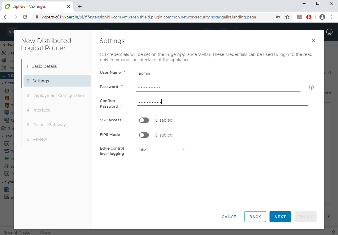
Provide Username and Password for the appliance and click Next
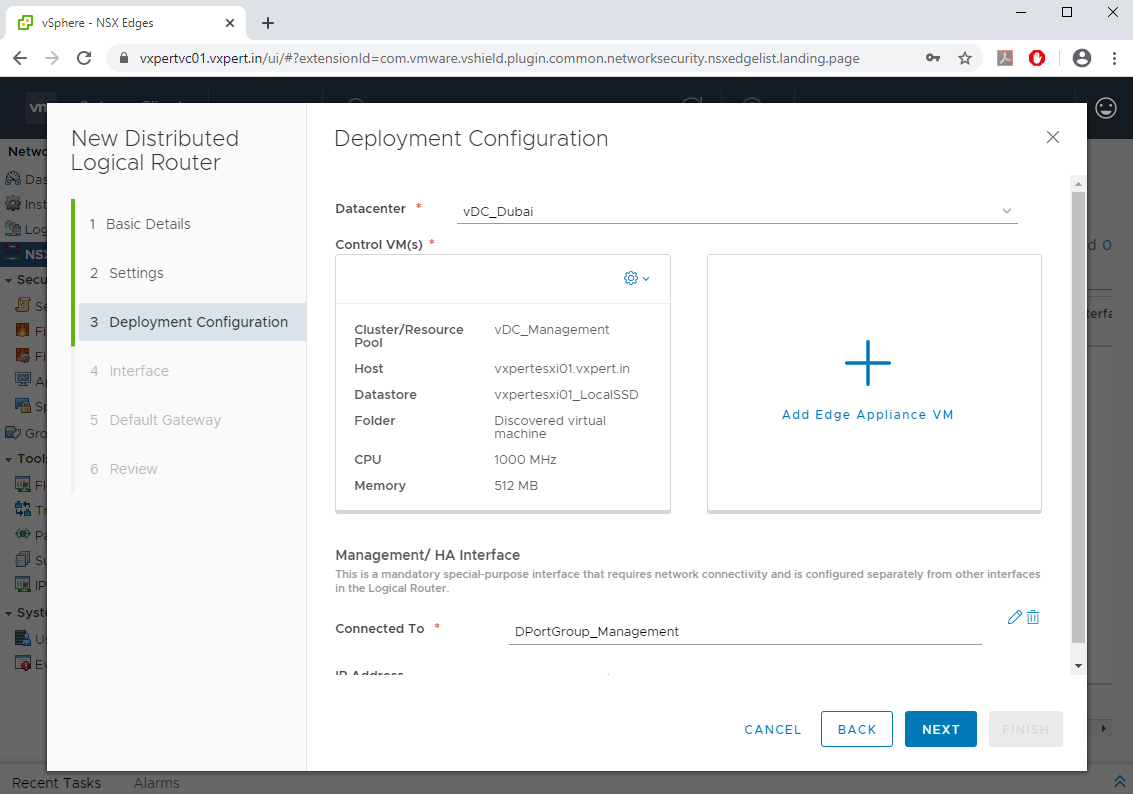
Select the Datacenter and click on Add Edge Appliance VM
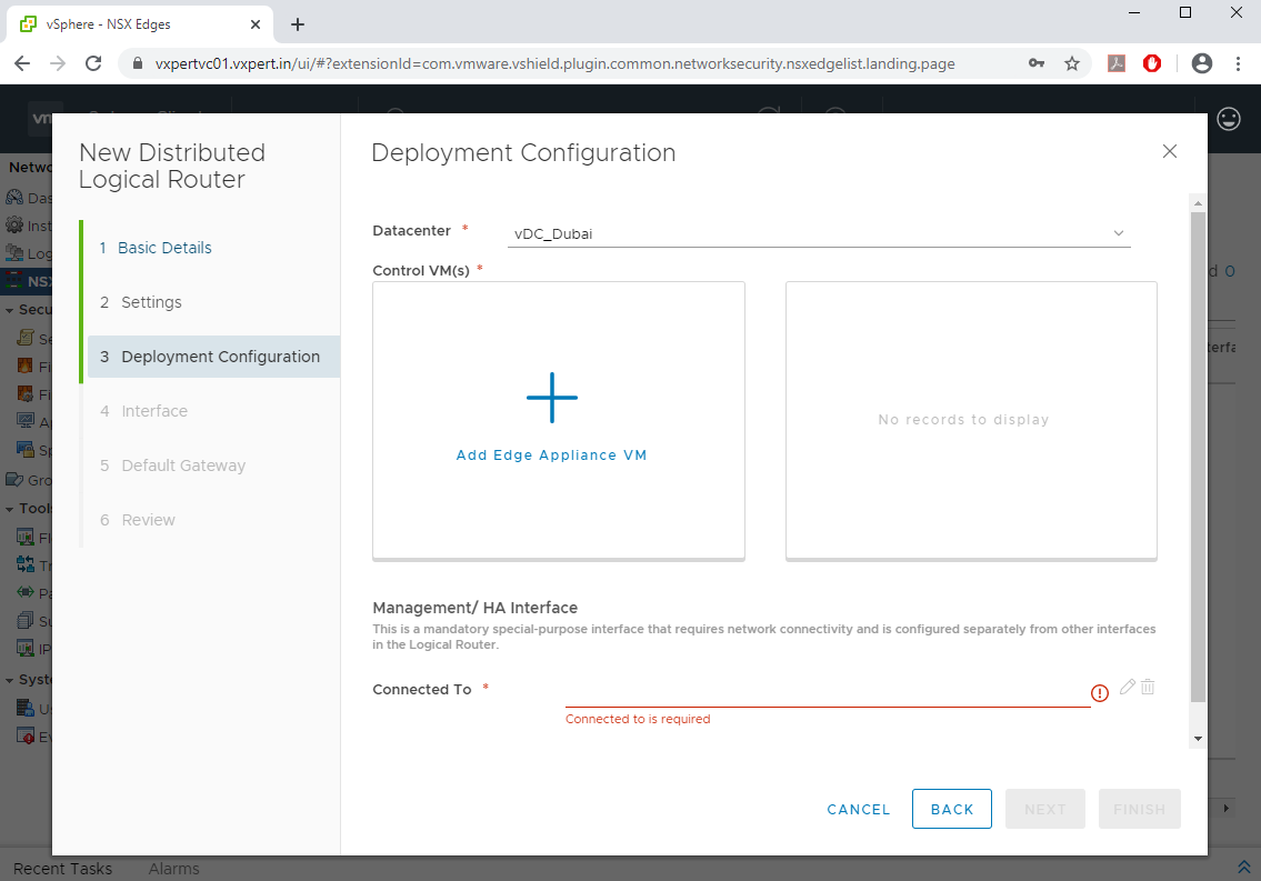
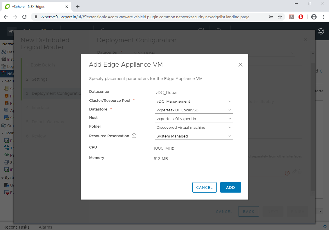
Select the Resource Pool, Datastore and ESXi host and click ADD
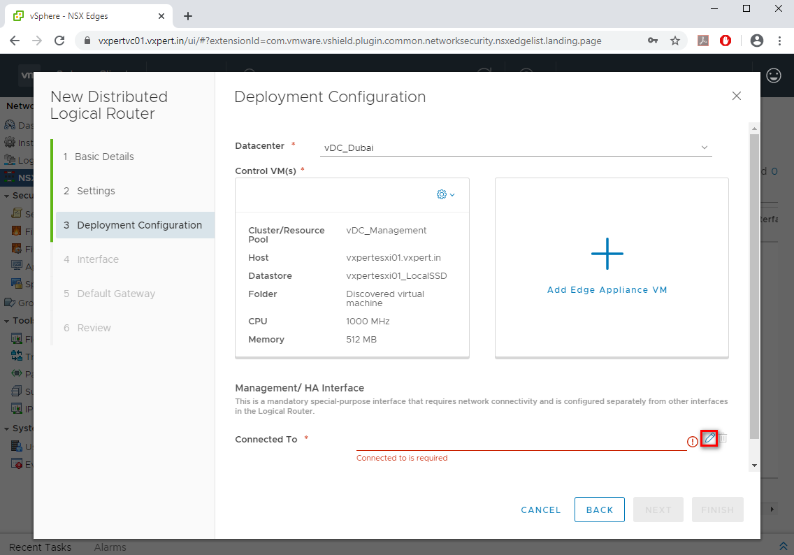
Select the Management interface for the Edge appliance by clicking the Edit button
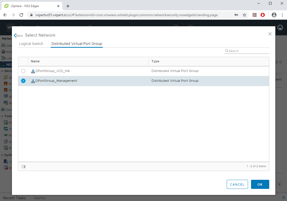
Select the Management switch and click OK
Click Next to proceed with the deployment
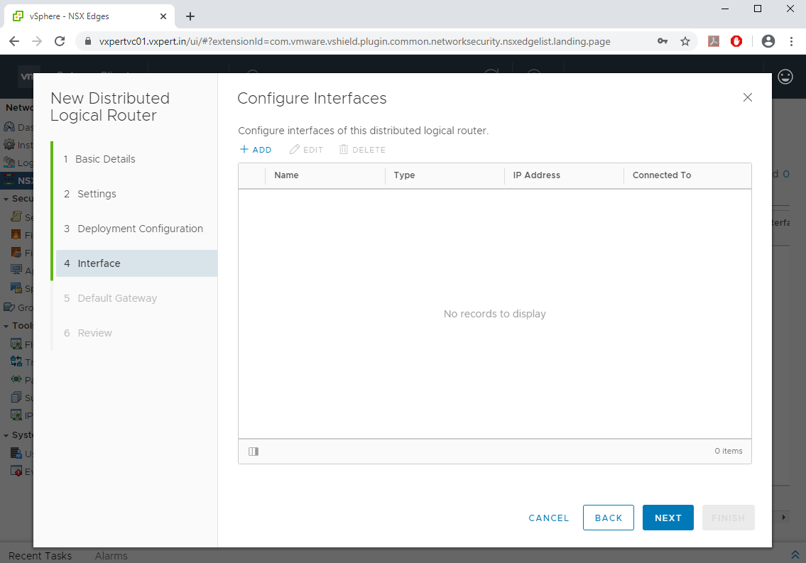
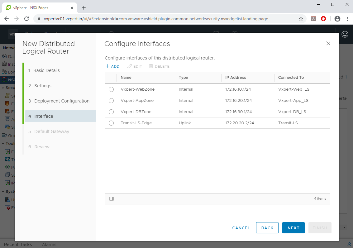
Here you will be configuring the Internal / uplink for Distributed Logical Router (DLR), Click on +ADD to configure the DLR.
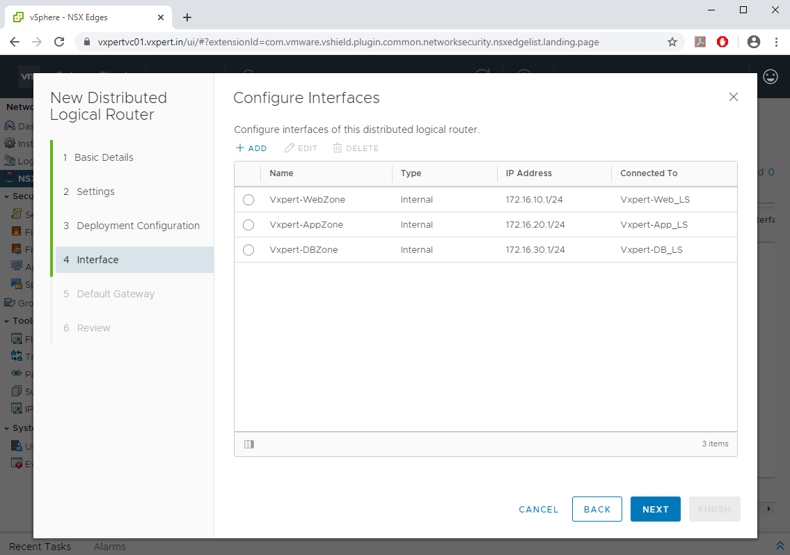
In this configuration I will be adding three internal networks for Web, App and DB which will be connected to the respective Logical switch created for them like below.
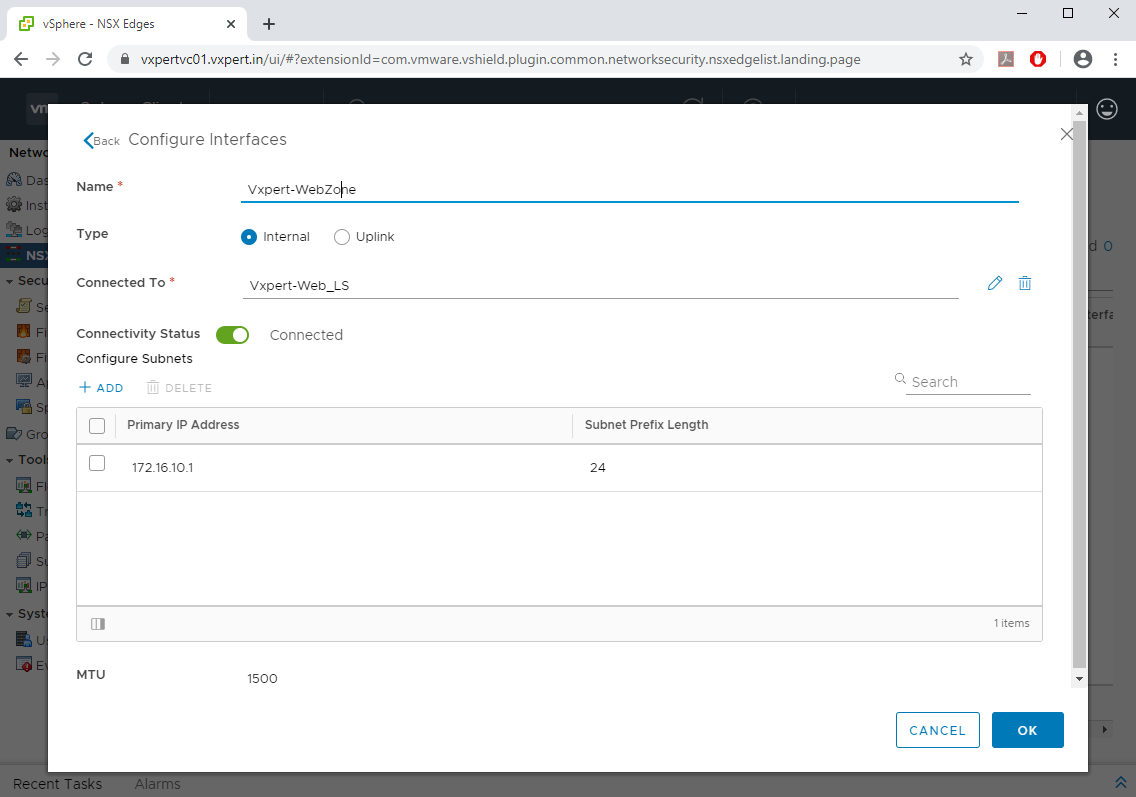
Repeat the same for other two Internal networks like App and DB
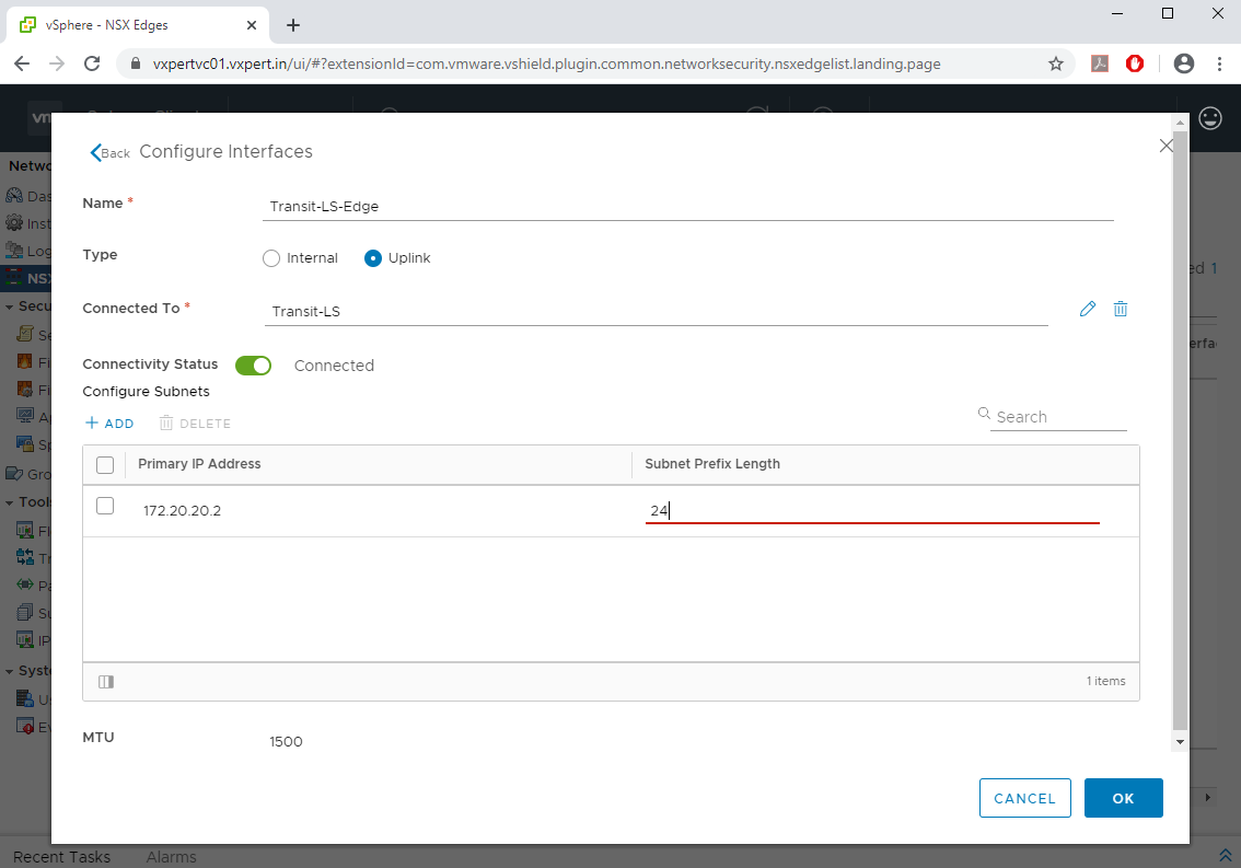
Now we must assign an uplink for Distributed Logical Router to connect the external world that is Edge Gateway. So, i will be creating a Transit Logical Switch which will act as an uplink of DLR
Now in the DLR configuration windows assign the uplink like below and provide the IP and click OK
Now we have configured all the Internal and External Networks for DLR, click Next
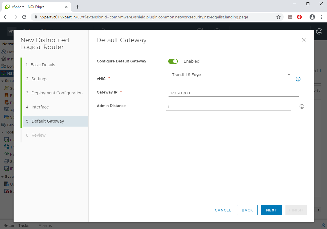
Here you will be configuring the Gateway for the DLR which is the Edge Gateway and click Next.
Review the configuration and click Finish to start the deployment.
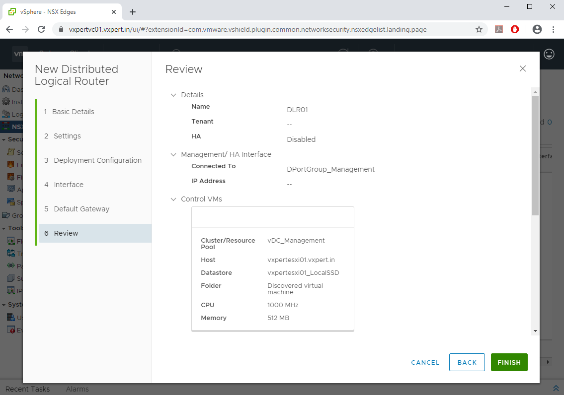
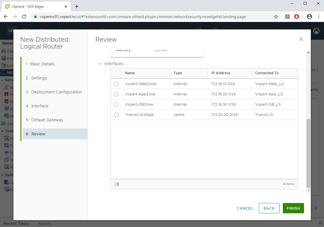
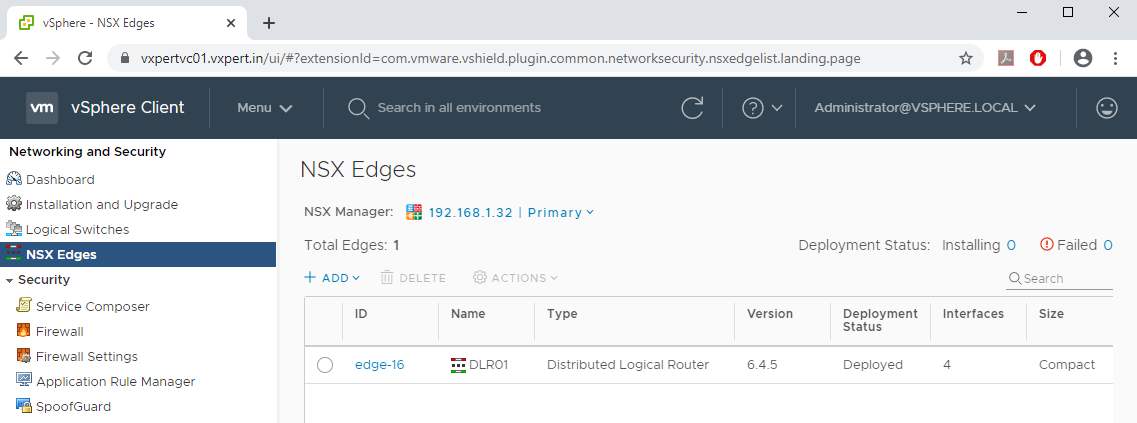
Once complete you can see the Distributed Logical Router Control VM in NSX Edges window
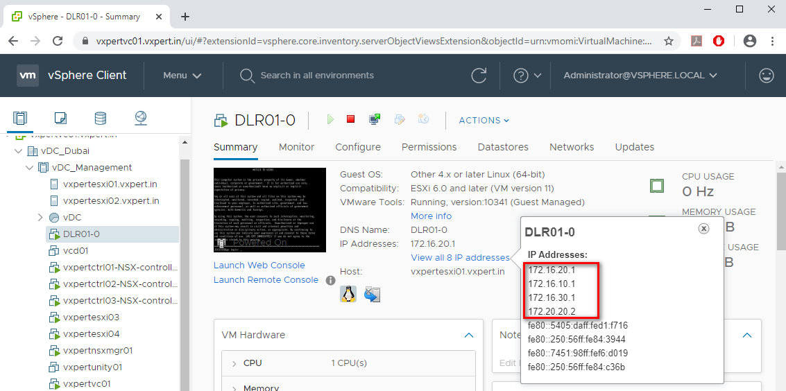
Also, on VM Network Interfaces you can see the IP Address configured for each zone and uplink.
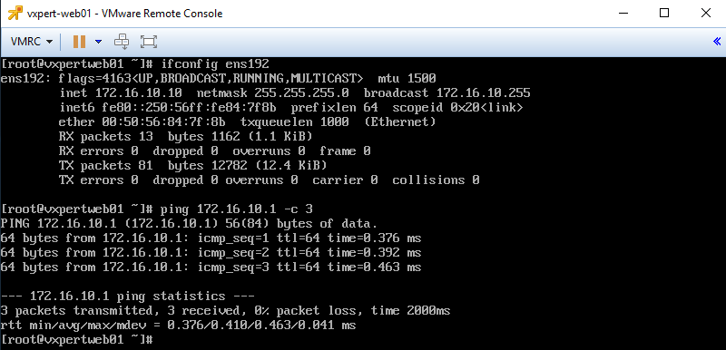
To test the functionality, you can assign the IP web01 server and check the DLR Gateway IP is reachable or not. You will be able to reach all Internal network Gateways but not the inside VMs .
To make this NSX series more understandable, i am splitting this in to multiple blogs
Part 2 – NSX Manager 6.4.x Installation & Configuration
Part 3 – How to Install Microsoft CA Signed Certificate In NSX Manager
Part 4 – VMware NSX 6.4.x Configuration
Part 5 – VMware NSX Logical Switching and DLR Configuration
Part 6 – VMware NSX Edge Configuration
Part 7 – How to Upgrade NSX Manager
Thanks,
If you have any comments, please drop me a line.
I hope this article was informative, and don’t forget to buy me a coffee if you found this worth reading.


Leave a Reply